Building an RTOS From First Principles
Contents
- Introduction
- Preamble
- Types of Memory and Fused Kernel-Preloaders
- A9 Hardware
- Important Specific Numbers
- Boot Sequence
- Allocator
- Scheduler
- Latency
- Limitations
Introduction
The ARM Cortex-A9 is a common microprocessor and shows up a lot as the integrated processor on smaller/older FPGA SoCs (think lower-end Zynq boards, Cyclone V, etc). It’s cheap, does microprocessor things reasonably well, has lots of support for interfacing with FPGAs, and tends to come in a nicely square-shaped package. It was also used in really old smartphones (the iPhone 4s A5 used two A9 cores, similar to the Cyclone V). The A9 was never designed for real-time work though, which is ironic given its prevalence in FPGA SoCs. To do real-time work on the A9 you basically have three options that run (mostly) out of the box:
- Embedded Linux - Not actually real-time and very bloated depending on what is needed
- FreeRTOS - Much leaner but not good for high utilization tasks, and its SMP support is recent and not available on every port (the A9 included)
- Zephyr - Leaner than Linux and more capable than FreeRTOS but still somewhat bloated
It would be nice to have a lightweight, efficient real-time scheduler. I do a lot of control and DSP work, so EDF is a good starting point for me because 1: it’s very good for hard periodic constraints and 2: it’s relatively underserved. Embedded Linux is completely inappropriate for it, FreeRTOS doesn’t natively support it, and Zephyr only uses it as a tiebreak, not as the fundamental scheduling primitive. I’d also like SMP if possible, as every A9 system I’ve worked with has been dual-core. Lastly, I’d like whatever gets built to be bootable off an SD card. For now we’ll ignore the FPGA side and assume it’s handled separately; eventually I’d like to pack the FPGA image onto the SD card and mount it as part of boot, but that can wait.
Alongside all this, I’d like to answer one question: just how inappropriate is the A9 for real-time work? I think it’s fun to make hardware do things it wasn’t designed to do, and I’ve been asked this before, to which I gave the standard safe answer: “the A9 isn’t designed for this, so keep all real-time functionality on the FPGA regardless of how fast it needs to run.” I still think that was probably right, especially since we had to run Linux on the A9 in that case anyway. But a more conclusive answer would be nice, so getting one seems worthwhile.
This project can balloon fast, so an 80/20 on the core components is the best use of time if you’re not building a commercial-grade system (I don’t want to maintain or sell this. I just want to see an A9 do dual-core EDF and pack the whole thing onto an SD card).
With all that said here’s the (actual) preamble.
Preamble
We will build the thing for a Cyclone V (DE1-SoC) because that’s what I currently own. Later on this may be extended to accommodate other systems as well but we’ll only worry about this one for now.
We will assume the following basic operational behaviour is expected:
- Kernel + application code is loaded into SD card.
- SD card goes in SD card slot.
- The system boots from the SD card whenever it’s power cycled after which it proceeds to run the application code. It’s assumed the application code may make use of the kernel but it shouldn’t be a requirement.
- If a piece of hardware functionality is desired or not desired (caches, SMP etc), we pass these as compile parameters, we don’t change them at runtime.
Since we’re running on a real chip we need all the hardware initialized properly at the right times. Some of it is A9-specific (GIC, L1 caches), some is Cyclone V-specific (L2 cache, SDRAM PHY); all of it is covered later. We want to separate out the board-specific functionality so we can port to other systems more easily later on, which is the point of a board support package (BSP). Ours is minimal: its only job is to set up the standard Cyclone V hardware shared by both cores and useful for generic system operation. The kernel handles the rest of the initialization.
Disclaimer
This document assumes a reasonable degree of fluency with basic systems programming and computer science. If data structures or computer architecture aren’t yet intuitive, there are plenty of good guides online. The purpose here isn’t to “explain what an interrupt is”, but to “explain how you use hardware signals, data structures, and a known initial system state to build the low-level machinery most people take for granted when running a program”. There’s a lot to cover, so I’ll focus on the non-trivial parts and leave things like “did u know u can control piece of hardware by writing to register” as an exercise for the reader.
Types of Memory and Fused Kernel-Preloaders
All A9s have something called On-Chip RAM (OCRAM). It’s exactly what you’d expect, and is 64KB on the Cyclone V. A9s also have an interface for Synchronous Dynamic RAM (SDRAM), which lives off-chip; its implementation is up to the SoC manufacturer, since memory requirements change with the application. Lastly, the A9 has a special piece of memory called Boot ROM, whose job is to read data from something like an SD card and copy it into OCRAM. A preloader then runs from OCRAM, initializes the SDRAM hardware, and copies the rest of the code into SDRAM.
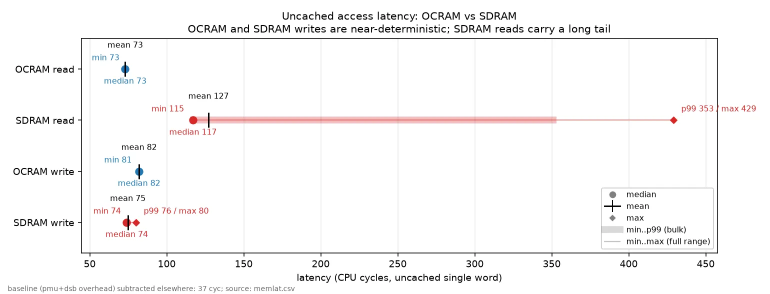
Normally the kernel is separate from the preloader and lives alongside the application code in SDRAM, but there’s no reason that has to be the case. We could keep a small kernel in OCRAM and let the distinction between preloader and kernel fall away. OCRAM is faster, so this is generally preferable, especially when strict real-time requirements rule out the caches: SRAM read latency is far more deterministic than DRAM’s, since you don’t have to wait on the DDR controller. We could move application code into OCRAM too if it were small enough, but it generally isn’t, so for now all appcode stays in SDRAM.
In short, we can fuse the kernel with what would normally be the preloader and run it from OCRAM to improve speed and determinism, especially with the caches off. For perspective, here’s a speed comparison:
A9 Hardware
As alluded to earlier, we are using a real A9 on a real SoC and so we have to worry about the physical hardware. Here’s a picture:
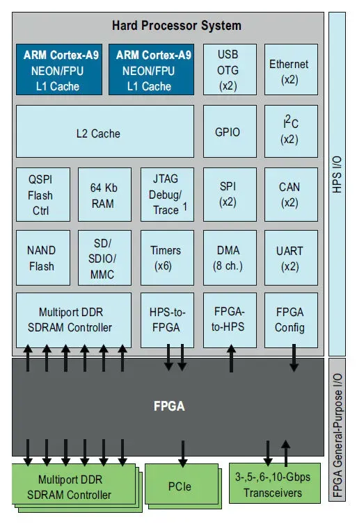
Not pictured are the Snoop Control Unit (SCU), which keeps both cores’ L1 caches coherent, and the MMU, which handles virtual-to-physical address translation and is required to engage the L1 data cache. Kairos uses both L1 caches, the L2 cache, and the SCU.
Important specific numbers
Some specific numbers that matter in various places:
- Stack Size: 8192 bytes per thread (
THREAD_STACK_SIZE = 0x2000, embedded in eachthread_t) - Heap Size: 16777216 bytes (
_heap_size = 0x01000000, carved out of SDRAM) - Gtimer ISR Frequency (scheduler tick resolution): ~1 kHz, i.e. ~1 ms per tick.
GTIMER_AUTOINC = 199999fires one IRQ every 200000 global-timer increments; at the MPU peripheral clock (~200 MHz, the MPU clock divided down) that lands near 1 kHz. - L1 I-Cache Size: 32768 bytes (32 KiB, 4-way set-associative)
- L1 D-Cache Size: 32768 bytes (32 KiB, 4-way set-associative, 32-byte lines)
Every hardware block that isn’t the A9 core itself sits at a fixed address in the system’s address map. You talk to each one by reading and writing its registers at these addresses. These are the DE1-SoC (Cyclone V) values; the emulated QEMU board differs (its shared-peripheral region starts at 0x1E000000 instead of 0xFFFEC000).
The shared-peripheral region (one block of hardware bolted onto the dual-core A9, base 0xFFFEC000):
- Snoop Control Unit, keeps the two cores’ L1 caches in sync:
0xFFFEC000 - Interrupt controller, the per-core side where a core reads and acknowledges the interrupt it was handed (GIC CPU interface):
0xFFFEC100 - Global timer, the counter whose comparator fires the scheduler tick:
0xFFFEC200 - Interrupt controller, the shared side that decides which core each interrupt goes to (GIC distributor):
0xFFFED000 - L2 cache controller (PL310):
0xFFFEF000
The rest of the chip’s hardware (the “HPS” peripherals):
- SD card controller, reads/writes the microSD card:
0xFF704000 - SDRAM controller, brings up and configures the off-chip RAM:
0xFFC25000(the register block it fills starts at0xFFC20000) - Clock Manager, the PLLs and clock dividers:
0xFFD04000 - Reset Manager, holds blocks (and the second core) in or out of reset:
0xFFD05000 - System Manager, misc. system glue, including where the second core starts executing:
0xFFD08000 - Scan Manager, used during SDRAM I/O calibration:
0xFFF02000 - Watchdog timer 0, resets the chip if we stop feeding it:
0xFFD02000 - L3 interconnect remap register, switches address
0x0from boot ROM over to SDRAM:0xFF800000
Boot Sequence
Here’s an overview of how the system boots.
Boot ROM to Reset Vector
All Boot ROM does is take a specific region of the SD card and copy it into OCRAM, then read a header at a fixed offset. On the Cyclone V that offset is 0x40, and the header needs 0x0C bytes reserved for it. We fill this zone in when building the SD card image, so we have to make sure no code or data lives there.
Once Boot ROM has read the header it moves the PC to the location the header specifies. We point that at 0x0, where the reset vector in our vector table lives. From there we jump to _reset_handler in kernel.s.
_reset_handler
The first thing we do is set the Vector Based Address Register (VBAR) to our vector table’s location.
ldr r0, =_vectors mcr p15, 0, r0, c12, c0, 0
Next we walk each stack and disable interrupts. We start the walk from a different place based on which core is running:
.if ENABLE_SMP != 0
    mrc p15, 0, r0, c0, c0, 5        @; MPIDR
    and r0, r0, #0x3                 @; core id
    cmp r0, #0
    ldrne r0, =_cpu1_und_stack_top   @; CPU1: its own stack bank
    ldreq r0, =_cpu0_und_stack_top   @; CPU0: top-of-OCRAM bank
.else
    ldr r0, =_cpu0_und_stack_top
.endif
    msr CPSR_c, #(MODE_UND | I_BIT | F_BIT)
    mov sp, r0
    ldr r1, =_und_stack_size
    sub r0, r0, r1

    msr CPSR_c, #(MODE_ABT | I_BIT | F_BIT)
    mov sp, r0
    ldr r1, =_abt_stack_size
    sub r0, r0, r1

    msr CPSR_c, #(MODE_FIQ | I_BIT | F_BIT)
    mov sp, r0
    ldr r1, =_stack_size
    sub r0, r0, r1

    msr CPSR_c, #(MODE_IRQ | I_BIT | F_BIT)
    mov sp, r0
    ldr r1, =_stack_size
    sub r0, r0, r1

    msr CPSR_c, #(MODE_SVC | I_BIT | F_BIT)
    mov sp, r0
    ldr r1, =_stack_size
    sub r0, r0, r1

    msr CPSR_c, #(MODE_SYS | I_BIT | F_BIT)
    mov sp, r0
Next we invalidate the L1 I-cache. The A9 requires this before we can enable it, but it’s easy: we just write to a register:
    mov r1, #0
    DSB
    mcr p15, 0, r1, c7, c5, 0
    ISB
The L1 D-cache is harder because there’s no bulk invalidate. It’s 32KB, 4-way set-associative, with a 32-byte line size, which means there are (32 * 1024) / 32 / 4 = 256 sets with 4 ways each: 256 distinct 32-byte lines, each of which can map to one of 4 locations in the cache. We invalidate all 256 sets on a per-way basis:
way_loop:
    mov r3, #0
set_loop:
    mov r2, r1, lsl #30
    orr r2, r2, r3, lsl #5
    mcr p15, 0, r2, c7, c6, 2
    add r3, r3, #1
    cmp r0, r3
    BGT set_loop

    add r1, r1, #1
    cmp r1, #4
    BNE way_loop
We then invalidate the TLB and enable branch prediction and data prefetch. They’re on by default right now, but could easily be made compile options later.
@; INVALIDATE TLB
mcr p15, 0, r1, c8, c7, 0

@; BRANCH PREDICTION ENABLE
mov r1, #0
mrc p15, 0, r1, c1, c0, 0
orr r1, r1, #(0x1<<11)
mcr p15, 0, r1, c1, c0, 0

@; ENABLE D-SIDE PREFETCH
MRC p15, 0, r1, c1, c0, 1
ORR r1, r1, #(0x1 <<2)
MCR p15, 0, r1, c1, c0, 1
DSB
ISB
The first time this code runs it’s on CPU0, because Boot ROM uses CPU0 by default and CPU1 is held in reset on power cycle. So we fail the following check and enter _cpu0_fork:
_cpu0_fork:
@; Zero BSS
    ldr r0, =_bss_start
    ldr r1, =_bss_end
    mov r2, #0
bss_zero:
    cmp r0, r1
    strlt r2, [r0], #4
    blt bss_zero

@; Zero the OCRAM host island (fault records, boot gate, SMP mailbox)
    ldr r0, =_host_shared_ocram_start
    ldr r1, =_host_shared_ocram_end
    mov r2, #0
host_ocram_zero:
    cmp r0, r1
    strlt r2, [r0], #4
    blt host_ocram_zero

@; RELEASE CPU1 -> it re-enters _reset_handler and forks on MPIDR
.if ENABLE_SMP != 0
 .if BOARD_IS_QEMU != 0
    nop
 .else
    ldr r0, =SYSMGR_ROMCODE_CPU1STARTADDR
    ldr r1, =_reset_handler
    str r1, [r0]                        @; cpu1startaddr = &_reset_handler (CPU1 re-enters, forks on MPIDR)

    ldr r0, =RSTMGR_MPUMODRST
    ldr r1, [r0]
    bic r1, r1, #RSTMGR_MPUMODRST_CPU1  @; deassert CPU1 reset -> CPU1 boots ROM -> _cpu1_spin
    str r1, [r0]
 .endif
.endif
At this point CPU1 is engaged: it branches to _reset_handler, runs all the cache invalidation, branch prediction, and prefetch code above, and jumps to _cpu1_fork, which we’ll discuss shortly.
After CPU0 turns on CPU1, it branches to cpu0_startup:
.if BOOT_TEST != 0
    bl ktrace_wait_boot
.endif
    bl cpu0_startup         @; RUN CPU0 STARTUP AND SET MAILBOX
void cpu0_startup(void)
{
#if ENABLE_SMP
while (!g_cpu1_ready){} /* wait for CPU1 in its spin loop before the remap below */
#endif
bsp_sdram_init(); /* PLL/scan-mgr/SDRAM/NIC301 -- prime self-boot suspect */
bsp_precache_init();
build_tables();
set_ttb_ptrs();
cpu0_gic_init();
cpu0_timer_start();
pmu_init();
heap_init(); // must precede psched_init(): it kMalloc's main_thread + the deque
#if ENABLE_SMP
g_cpu_mailbox_uncached = 1;
__asm__ volatile (
"dsb\n\t"
"sev\n\t"
);
while (g_cpu_mailbox_uncached != 2)
{
__asm__ volatile (
"wfe\n\t"
);
}
g_cpu_mailbox_uncached = 0;
#endif
__asm__ volatile (
"cpsie i\n\t"
);
psched_init();
}cpu0_startup first initializes the SDRAM PHY (a lot of code, most of it from U-Boot). That means starting the Cyclone V PLL machinery, configuring the IO ring that physically interfaces with the PHY, feeding inputs to the PHY’s control interface, running the PHY’s calibration sequence, specifying the size of the memory region, and remapping memory so that address 0x0 starts at the bottom of the SDRAM block instead of boot ROM. From here we can enable the SCU and L2 if desired, then build the page tables. We assume a direct mapping between virtual and physical memory. The page table supports two levels of granularity; we only use the finer level to mark specific sections uncacheable, mainly for system diagnostics read over JTAG. We set the TTB pointers so we know where the page tables are, initialize CPU0’s GIC and timers, start the PMU (important for the scheduling policy later), initialize the heap, and wait for CPU1 to signal that it’s ready before engaging the scheduler (which needs both cores live under SMP).
_cpu1_fork:
.if ENABLE_SMP != 0
    .align 2
    ldr r0, =g_cpu1_ready
    mov r1, #1
    str r1, [r0]                        @; publish: CPU1 is off the 0x0 alias, in OCRAM
    dsb
    ldr r0, =g_cpu_mailbox_uncached

    wfe
    1:  ldr r1, [r0]
        cmp r1, #0
        bne engage
        wfe
        b 1b

    engage:
        bl cpu1_startup
        cpsie i

        ldr r0, =g_cpu_mailbox_uncached
        mov r1, #2
        str r1, [r0]
        dsb
        sev

        bl cpu1_main
.endif
Across these two routines, CPU0 first signals CPU1 that it’s ready for CPU1 to run its startup routine, which sets up the TTB pointers, GIC, timers, and PMU just like cpu0_startup. It then waits for the completion signal. To save power, the wait/signal handshake uses the wfe and sev instructions together with a shared mailbox so neither core breaks out on the wrong event. CPU0 initializes the scheduler once CPU1 has finished its startup routine. By then CPU1 may or may not be in its main loop. That loop is empty: CPU1 is expected to run tasks only through the scheduler. CPU0’s main loop holds the application code and can assign tasks to CPU1 as needed, and any task running on CPU1 can assign more tasks too.
Allocator
Kairos includes a Two-Level Segregated Fit (TLSF) allocator. The idea is to divide free memory into a fixed number of size classes. When an allocation is requested, its size is rounded up to the smallest class that can accommodate it. The allocator then finds a free block belonging to that class or a larger one and carves out the requested memory. Any remaining memory is returned to the appropriate size class, where each block is guaranteed to be at least as large as its class’s lower bound, but strictly smaller than the next class’s lower bound.
The allocator is initialized with the entire heap represented as a single free block in the largest size class. To satisfy an allocation, it searches for an available block in the requested class or any larger class. Since there are at most C size classes, where C is constant, and splitting a block takes O(1) time, allocation is bounded by O(1) time.
The diagram below illustrates this process:
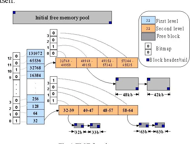
In more detail: there are two levels of granularity. Buckets progress as powers of 2, and bins split each bucket evenly into 32 size classes. One bitmap marks which buckets hold any free block, and a per-bucket array of bitmaps marks which bins inside it are free. Finding the first usable bucket is just locating the leading one in the bitmap; from there we compute the excess, find the first bin in that bucket big enough for the request, and scan bins and buckets upward from that minimum for the first free block.
When we carve out a block, we re-map the remainder to the largest bucket-bin pair it still fits, set the relevant bits if nothing free lived there before, and clear the old bucket/bin bits if that block was the last free one of its size. Free blocks in each class live in a doubly linked list, so with m buckets and n bins there are at most m×n active free lists.
Each free node needs at least 16 bytes: 4 for the size, 4 for the logical predecessor, 4 for the logical successor, and 4 for the previous physical block’s address. That last field is what lets us coalesce backwards. Say a block of size k is freed directly in front of a free block of size s: we want to drop the s entry and make one (k+s) entry, but to check whether the block behind us is free we need its physical address. Coalescing forwards is free because we already know our own size. Since every free block is at least 16 bytes, the minimum allocated block is also 16 bytes: the size and previous-physical address sit in the first 8, followed by an 8-byte minimum payload, whose first 8 bytes become the next/prev pointers once the block is freed.
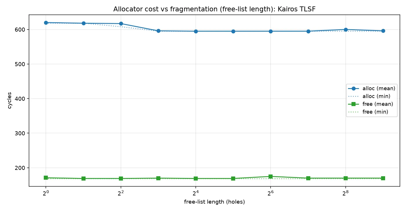
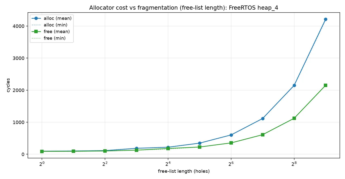
To put TLSF’s advantage in context, we compare it against a simple free-list allocator under fragmentation: FreeRTOS’s heap_4, which keeps a single free list in address order and traverses from the base on every allocation to find the next viable free block (O(N)). We surface the worst case by allocating more and more blocks before the timed allocation.
Scheduler
Kairos uses a hybrid Earliest Deadline First (EDF) / Round-Robin (RR) scheduler. Tasks with real-time mandates go through the EDF path, which always takes priority over the RR path. To do that we use two min-heaps: the first manages released tasks by earliest deadline, the second manages unreleased tasks by earliest release time. If a core’s global tick count is past a task’s release time, that task is released and runnable. This lets us decompose each scheduler interrupt into the following steps:
-
We set up a global (shared) timer during board init. It has a comparator that periodically fires an IRQ and writes an interrupt code to a register. On receiving the IRQ, provided all the relevant GIC machinery is primed to accept it, the A9 moves the PC to a fixed offset from the VBAR. Our
_irq_handlerlives there. We check that the IRQ code matches the gtimer code; if it does, this is a scheduler preemption and we invoke the appropriate routine. -
The scheduler routine runs in IRQ mode (
0x12) while task code runs in SYS mode (0x1F). Sospsrandlrhold the last SYS-mode CPSR and PC from before preemption. We usesrsfdagainst SYS-mode identifier0x1Fto push that CPSR and PC onto the SYS-mode stack from IRQ mode. r0-r12 are shared across modes, but r13 and r14 (sp and lr) are banked, so we have to switch to SYS mode before pushing anything else (to advance the right sp), and we have to push r0-r12 before running any interrupt code so the register state doesn’t get clobbered. Note that all ARM exceptions add a fixed offset to the exception mode’s lr; IRQ adds +4, so that has to be undone before we can recover the SYS-mode PC.
    sub lr, lr, #4 @; get lr_irq i.e. get the last pre-interrupt PC value
    srsfd sp!, #0x1f @; Store Return State Full Descending --- push cpsr then pc (cached spsr then lr_irq in this case) onto sysmode stack (specified by 0x1f), sp autodecs

    cps #0x1f @; Change Processor State --- switch to system mode

    push {r0-r12} @; store the FULL integer register file. A context switch resumes a
                  @; DIFFERENT task, so r4-r11 (callee-saved, live across the interrupted
                  @; task's calls) must be part of the saved context -- saving only the
                  @; AAPCS caller-saved set corrupts a resumed task's r4-r11.

    push {lr} @; push lr_sys onto sysmode stack


cps #0x12-
Check the FIFO for any tasks that haven’t been added to the scheduling pool yet. If a task is RT, release it immediately and add it to the deadline heap. If it’s not RT, add it to the appropriate RR FIFO based on priority.
-
Check the release heap for any releasable tasks. We always catch them the first cycle they become releasable, because the ticker increments inside the scheduler routine. When one is releasable, pop it from RelHeap, set its deadline to the current tick plus its period, and add it to the deadline heap.
-
Pop the first runnable task from the deadline heap; it’s guaranteed to have the earliest deadline. If it’s finished and aperiodic, remove it from the heap and add it to the outgoing_threads FIFO. If it’s finished and periodic, increment its release time by one period and move it to RelHeap if that release time is still in the future, or DeadHeap if it isn’t.
-
If the deadline heap is empty, all its tasks are finished, or nothing is released yet, check the high-priority FIFO, then medium, then low, and choose the highest-priority task available. If the same persistent task has been picked over others of its priority for as many ticks as its period, rotate it to the back of its FIFO and check whether the next task is runnable. Remove any task that’s no longer runnable. Repeat until a runnable persistent task is found or all tasks have been removed.
-
If no task has been found by this point, set the current system sp to that core’s main sp.
-
Switch back to SYS mode and pop from sp: first restore lr and r0-r12, then call
rfefd sp!to restore pc and cpsr. The context switch is now complete.
Not mentioned above is the servicing of the GIC machinery to (a) re-enable IRQs when desired and (b) re-enable interrupts from the gtimer source.
The tick comes from the A9 global timer. At board init (cpu0_timer_start) we stop the timer (GTIMER_CTRL = 0), clear any stale event (GTIMER_ISR = 1), set the auto-increment reload to GTIMER_AUTOINC = 199999, point the comparator one period ahead (GTIMER_CMPL = current count + 199999), then write GTIMER_CTRL = 0b1111. The four control bits are, from the bottom: timer enable, comparator enable, IRQ enable, auto-increment. CPU1 (cpu1_timer_start) sets the same bits except the timer-enable bit: the counter is global and already running, so each core only needs its own comparator and IRQ enabled. Auto-increment is what makes re-arming free: when the comparator matches, the hardware advances it by AUTOINC + 1 on its own, so the ISR never has to reprogram GTIMER_CMP.
Acknowledging a tick is therefore two levels. The asm _irq_handler first calls _identify_and_clear_source, which reads GICC_IAR (this acknowledges the interrupt at the GIC and returns its ID) and writes it straight back to GICC_EOIR (end-of-interrupt, which drops the running priority so the next tick is allowed to preempt). The ID is handed to c_irq_handler; for the gtimer source it writes GTIMER_ISR = 1 to clear the event flag at the timer itself, then calls next_thread(). So the GIC side is serviced in _identify_and_clear_source and the timer side in c_irq_handler, and the comparator re-arms itself.
Under SMP, the load balancer tracks utilization and assigns each new periodic task to whichever core has lower utilization at the time. An EMA filter smooths the utilization estimate so it’s less volatile. Persistent tasks can also be pinned to the lower-utilization core (or arbitrarily, if desired), but they don’t contribute to the utilization estimate themselves. This leads to two important points:
-
If overall per-core utilization goes over 1.0, the system is unpredictable
-
If persistent tasks are not pinned wisely or the cores are otherwise very high-u they may be starved.
So periodic tasks should be written like periodic ISR code: keep only the minimum necessary computation inside the task, and leave the period ample slack. For realistic workloads this is generally very doable.
Schedulability Bounds
Kairos’ utilization tracking and load-balancing systems are based on this paper, which proves the Liu and Layland EDF Schedulability guarantee for single core processors. Math summary:
Assume independent periodic tasks, where task releases a job every ticks, each job needs ticks of compute, the deadline is the end of the period (), and the processor is single-core. Define the processor utilization as the fraction of time the tasks demand:
The paper’s deadline-driven scheduling algorithm is just EDF: at any instant, run the released job whose deadline is nearest. Liu and Layland’s result (their Theorem 7) is that this is an exact test:
In other words the least upper bound on utilization is a full 100%: EDF can use every spare cycle. The two directions are both easy to see over one hyperperiod :
- Necessity. In ticks task releases jobs, so the total compute demanded is . If that demand exceeds the ticks available, so no algorithm can meet every deadline.
- Sufficiency. Their Theorem 6 shows EDF never leaves the processor idle before a missed deadline (an “overflow”). So if any idle time exists, which it must when , since demand , there can be no overflow, and every deadline is met.
This also makes EDF optimal: if a task set is schedulable by any algorithm at all, it is schedulable by EDF. Contrast this with a fixed-priority scheme like rate-monotonic (where we run the next ready task with the shortest period), whose guaranteed bound (also from this paper) is only
so RMS can be forced to miss deadlines at ~69% load (nice) while EDF is still fine. As long as a core stays at or below it’s provably schedulable, and the headroom is the slack the round-robin persistent threads and any new periodic tasks run in. At EDF still meets every deadline, but there’s zero slack, so we avoid that state.
Intuitively: say you have one task that takes 0.9s and has a 1s period. That leaves 0.1s of slack each period. Now add a second task that takes 1s and has a 10s period. You’d need 10 of those 0.1s slack intervals inside that 10s window, and since task 1 has a 1s period, you get exactly 10:
Now shorten task 2’s period to 9s. You can no longer fit 10 of those (0.9, 1) cycles into the 9s window, so there’s never enough slack to finish task 2 in time, and the set isn’t schedulable.
The figures below show EDF running on real hardware at different utilizations:
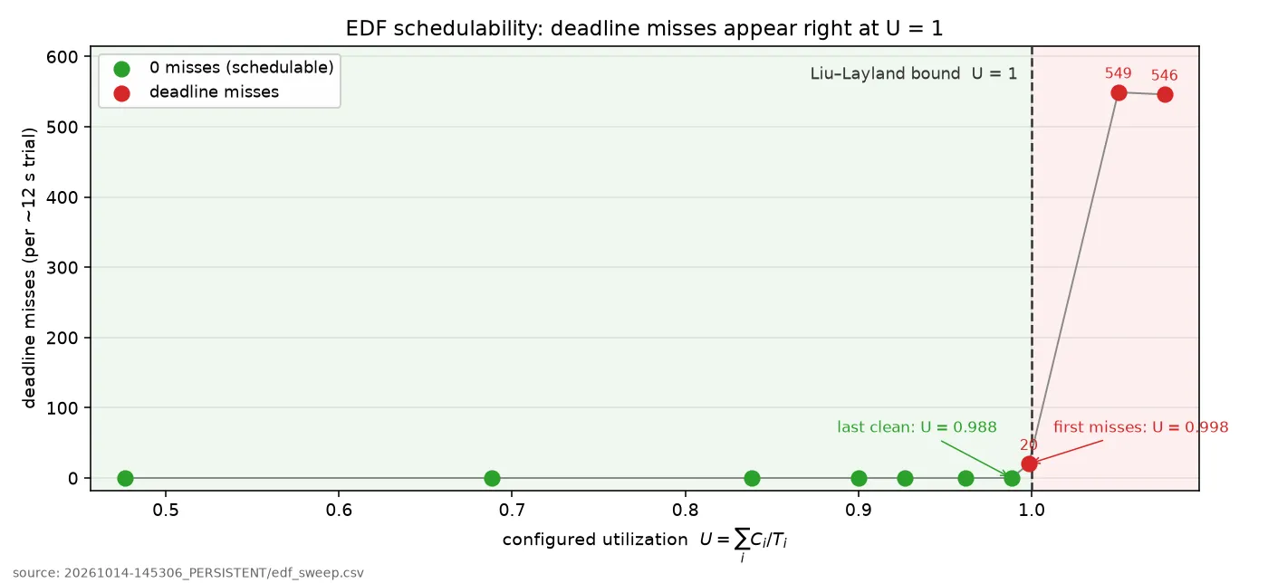
The taskset runs completely clean up to and only starts missing right as reaches 1. It starts missing before because of scheduler overhead. We showed for , but that ignores the time real schedulers spend on context switches, which eats into the slack. The real budget for task 1 looks more like , where the last coordinate is time spent in the scheduler. That overhead isn’t even constant: it depends on the state of the EDF heaps, SDRAM access latency (thread control blocks nominally live in SDRAM, which as shown above doesn’t give constant read latency), and any heap operations (freeing outgoing threads, say, which could be moved to a garbage-collection routine to preserve determinism if desired).
Interleaved IRQs
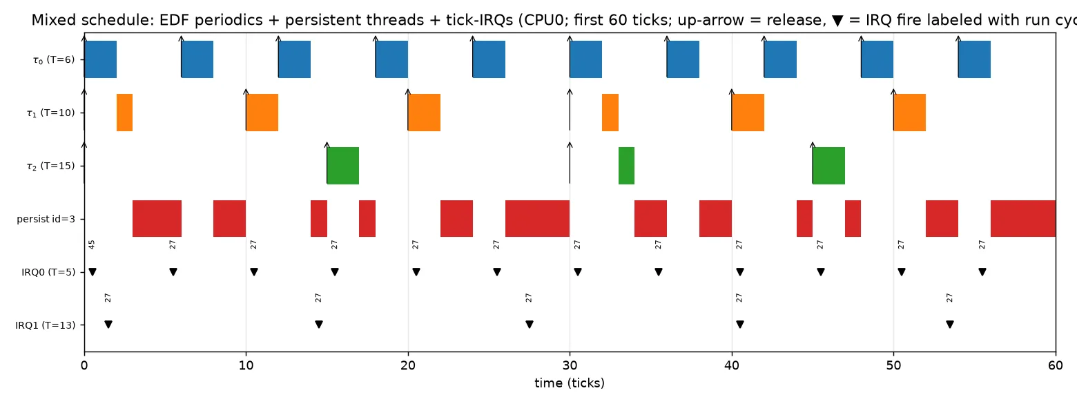
Right now we have periodic tasks and tasks with a deadline (“do this by this time”), and we re-release finished periodic ones once their old deadline expires. It would be nice to also have a basic “when this happens, do this” mechanism, ideally generic (so we can create new ones arbitrarily at runtime) and lightweight (so there’s minimal distance between “thing happening” and “other thing being done”). One way to do it is a tick-driven interrupt that fires when the tick counter reaches some deadline value. We can use min-heaps here too, so we always know the next upcoming interrupt. These interrupts take priority over EDF and RR tasks, run in IRQ mode, and are always serviced before the SYS sp is switched to the next stack. They have no stacks or register state of their own, since they’re just function calls in c_irq_handler.
We need to be careful though, because if two interrupts need to be run at the same time one will temporarily block the other. To prevent this, we make the following assumptions:
- Interrupts mounted at arbitrary start time during runtime i.e. the first interrupt can occur whenever, it’s the period we care about.
- We design the system such that interrupt frequencies are harmonics of each other
- We assume no interrupt takes longer than a Worst-Case Execution Time (WCET) of ~4096 CPU cycles. We set
WCET_TICKSto 1 tick, which at the current 1ms tick rate is far more cycles than that, so we’re being very generous. If more resolution is needed, the tick rate can be changed via the gtimer parameters at boot. - Interrupt period is defined in ticks and a zero period is invalid so that means each interrupt must have a period of at least one tick.
- The max number of interrupts is set to
MAX_IRQS. Right now this constant is 100.
sys_exit_e  mount_tick_irq_to_core(irq_t* irq, cpu_core_e core, sys_exit_e (*func)(void), uint32_t period, uint32_t id)
{
    if (period == 0) return SYS_ERROR;

    irq->core = core;
    irq->func = func;
    irq->timing.period = period;
    irq->id = id;

    lock_mutex_persistent(&g_cpus[core].core_mutex);

    if (g_cpus[core].irqHeap->curr_index == MAX_THREADS) //Heap full = no free spots
    {
        unlock_mutex(&g_cpus[core].core_mutex);
        return SYS_ERROR;
    }

    for (size_t i = 0; i < MAX_IRQS; i++) //Should always find something
    {
        if (g_cpus[core].avail[i] == NULL) //Found free spot
        {
            if (i == 0) //First position is free
            {
                if (g_cpus[core].irqHeap->curr_index > 0) //There must be other nonfree entries ahead of this one
                {
                    size_t j = 1;
                    while (j < MAX_IRQS)
                    {
                        if (g_cpus[core].avail[j] != NULL) break;
                        j++;
                    }

                    irq_t* next = g_cpus[core].avail[j];
                    uint32_t rel = next->timing.release_time - (j * WCET_TICKS);

                    while (lt_wrapped(rel, g_cpus[core].ticks)) rel += next->timing.period;

                    irq->timing.release_time = rel;
                }

                else //no tick irqs mounted yet
                {
                    irq->timing.release_time = g_cpus[core].ticks; //Will fire next sched preemption
                }
            }

            else //space directly behind was taken
            {
                irq->timing.release_time = g_cpus[core].avail[i-1]->timing.release_time + WCET_TICKS;
            }

            g_cpus[core].avail[i] = irq;
            irq->md.avail_index = i;

            break;
        }
    }

    min_heap_insert_node(g_cpus[core].irqHeap, (void*)irq, irq->timing.release_time);
    irq->md.status = IRQ_ARMED;

    unlock_mutex(&g_cpus[core].core_mutex);
    return SYS_OK;
}
When mounting an IRQ we use an array of size MAX_IRQS, initially empty. The first IRQ takes index 0. Each later mount walks until it finds the first free index, then sets its release time to WCET_TICKS past the release time of the previous entry. The one edge case is when index 0 has been unmounted but other live entries remain. Suppose the next one is at index k: we need to preserve k * WCET_TICKS ticks of separation between the two release times so we can greedily insert k-1 new entries between them later if needed. To do that we take entry k’s release time, wind it back by k * WCET_TICKS, and keep adding entry k’s period until it’s past the current tick. The new entry’s release time is then both in the future relative to our current tick count and exactly k * WCET_TICKS before some release of entry k, maybe not the next one, but by assumption 1 that’s fine. An alternative would be to pick an initial reference value at the start and compute offsets from it, but then calculating release times needs either division or repeated addition with a growing number of operations as the tick counter climbs. Both are undesirable.
Below is a figure demonstrating the IRQ interleaver in conjunction with the two task families:
Latency
Here are some figures for IRQ latency and context-switch cost:
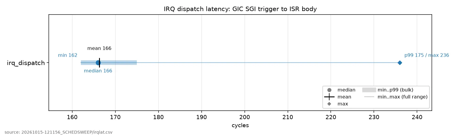
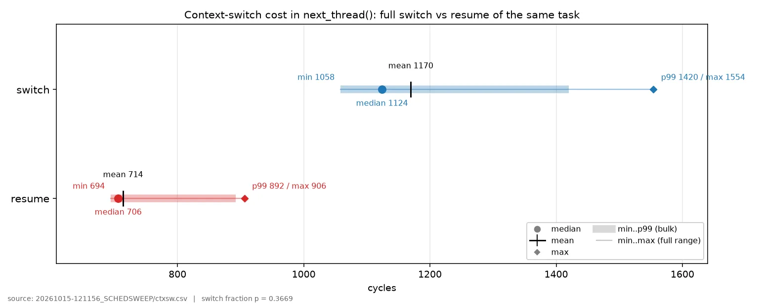
The A9 runs at 800 MHz, so each cycle is 1.25 ns. The global timer runs at a quarter of the MPU clock (200 MHz), and AUTOINC = 199999 gives one IRQ every 200000 counts, i.e. 1 kHz. We measure latency with the Performance Monitoring Unit (PMU)‘s cycle counter, so every number below is a count of 1.25 ns cycles.
IRQ dispatch has a 166 cycle median (~0.21 µs), with essentially everything inside 162–175 cycles and a single worst sample over 1024 trials of 236 cycles (~0.30 µs). The context switch inside next_thread() either resumes the same task or starts a new one. Starting a new one can require O(log n) heap operations, so it is slower and more variable: resuming costs ~706 cycles median (~0.88 µs), switching ~1124 cycles median (~1.41 µs), tailing to 1554 cycles (~1.94 µs) in the worst case. That is for one workload (3 periodic tasks, no persistent ones); we’ll see shortly that the switch cost climbs as the EDF heap fills.
For real-time work the timing variance matters more than the latency. IRQ dispatch varies by ~70 cycles (~90 ns) across its whole range, the switch by ~500 cycles (~0.6 µs), and both have short tails rather than fat ones. Against the 1 ms scheduler tick (200000 cycles) the worst-case switch is 0.8% of a tick and the worst-case IRQ dispatch is 0.12%. For periodic control/DSP work in the kHz range the per-event jitter sits three to four orders of magnitude below the deadline.
FreeRTOS on a Cortex-M quotes ~86 cycles for its context switch in its own FAQ, and independent measurements land around ~220 cycles on a Cortex-M4. However, a Cortex-M4 runs at ~168 MHz (the part those numbers come from), so ~86–220 cycles is ~0.5–1.3 µs of wall-clock, comparable to our ~1.41 µs. The surprise is that we hit that on a dual-core A9 that drags caches, an MMU, and SMP coherence along while saving the full register file by hand. In absolute time we’re basically even with the Cortex-M RTOS everyone benchmarks against. The one place the Cortex-M flatly wins is interrupt entry: its NVIC reaches the ISR in a hardware-fixed 12 cycles (~70 ns) with zero jitter, where our GIC path is ~0.21 µs with a small tail. The GIC just isn’t built to guarantee fixed, low-latency entry, and there’s nothing we can do about that.
The verdict: for the firm/soft real-time periodic workloads this targets, the jitter is comfortably sufficient, negligible against millisecond-scale deadlines, and competitive in absolute time with FreeRTOS on a Cortex-M. This is a genuinely surprising result for a chip supposedly unfit for real-time usage. Where it would fall short is sub-microsecond hard determinism, tight interrupt-to-pin response, or MHz-rate edges, where the GIC tail and cache jitter matter and a bare Cortex-M (or the FPGA fabric) is the right tool, which is exactly the work you’d want to keep off the A9 anyway.
The Kairos EDF scheduler uses min-heaps, which carry an O(log n) worst case versus the O(1) of the simpler RR scheduler. But those are worst cases, and most of the time a preemption doesn’t switch tasks, so the average preemption overhead is still comparable.
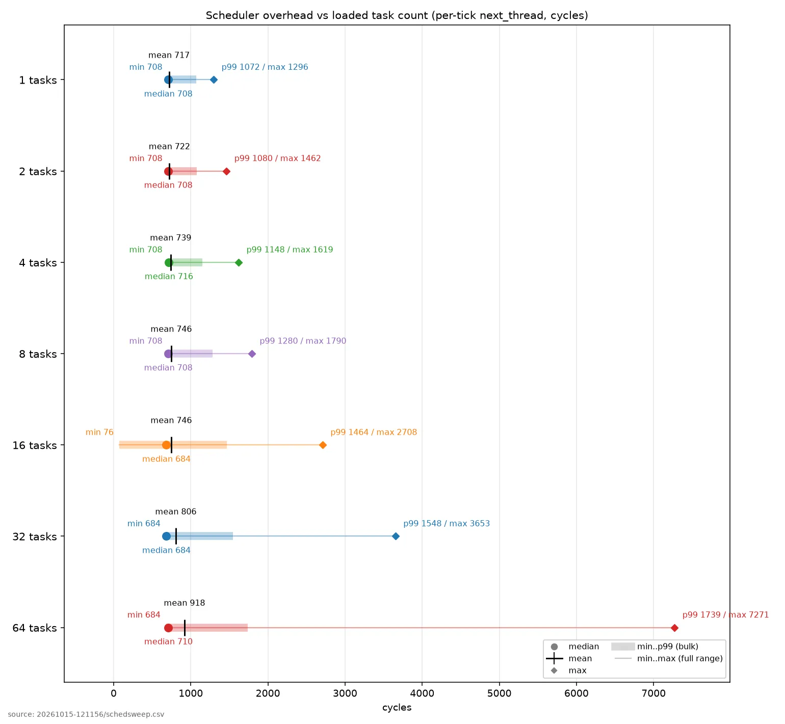
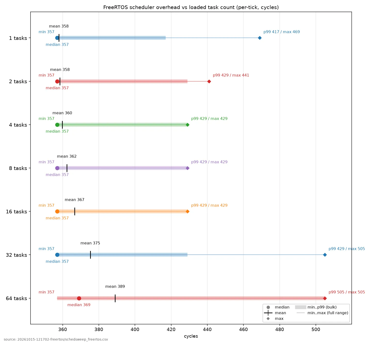
As we’d expect, fixed-priority is the cheaper and flatter scheduler here, roughly 2x less per tick at the baseline and a worst case that does not grow with the taskset. Kairos pays that premium for dynamic deadline ordering, the thing fixed-priority structurally cannot do, plus the dual-core balancing and the persistent class layered on top. And the premium is small against the deadline it has to clear: even Kairos’s worst tick at 64 tasks is 3.6% of the 1 ms tick (200000 cycles), where FreeRTOS sits at 0.25%, so neither scheduler is anywhere near being the bottleneck for the kHz-scale periodic work this targets.
And if you only need plain round-robin scheduling, Kairos supports that too, just like FreeRTOS.
Limitations
If it wasn’t already apparent, this isn’t a production-ready kernel. Here’s a non-exhaustive list of limitations:
- It is currently only ported for the Cortex-A9 implementation on the Cyclone V SoC
- All real-time bounds are empirically derived, not formally verified
- The kernel is not robust at all
- The only synchronization primitive currently provided is a binary semaphore with a few different penalty mechanisms
- The test code is kind of a mess
- Nothing set up for peripherals/other timers/other processor modes atm
- Did I mention the thing isn’t robust?
The worst-case context switch is noticeably less favourable to EDF, as we’d expect. We also don’t currently stagger EDF tasks, so many can get released or terminated on the same tick. That’s less than ideal; a staggering mechanism like the IRQ interleaver, letting runtime-declared tasks release on different ticks, would help. It would also be good to support static tasks and tick-driven IRQs that don’t have to be created at runtime (like most self-respecting RTOSes), so they could be staggered as needed, but that was less exciting to build so I haven’t gotten to it.
The reality is I’ve worked on this on and off for a few months now, and most of the reward has come from two things: implementing the kernel by hand (because I’m weird and I like doing this stuff), and the joy of watching an A9 do things it was never advertised to do. The marginal effort-to-learning ratio of going from where this is now to something you could mistake for a hardened production system isn’t worth it for me, and I want to start on other things. So I’m releasing the project as-is with no guarantees of further updates. The code is here, and I’d happily welcome any discussion of test accuracy and the like. The harness is kind of jank, but if you have a DE1-SoC and an SD card you should be able to run everything and reproduce my results with minimal effort.
There’s also the obligatory AI disclaimer. Most of the test code was written by Claude; most of the BSP code was either written by Claude or stitched together by it from old Intel/Altera/U-Boot code. Pretty much the entire kernel was written by hand, though I’m sure Claude could improve it from its current state. I split things this way to get the highest amount of learning per unit time. If I wanted to completely master the Cyclone V I’d do everything by hand; if I were shipping a product I’d lean on Claude more. For me, at this point, this is a happy middle ground, and I’m satisfied with the outcome.